The MF70 is a great machine and ideal for a beginner conversion. However, I soon found one limitation – the Y axis is limited to a tiny 48mm. I kind of assumed that the 70 in the name of the mill (and also the separate KT70 compound table) meant 70mm, but it seems not.
A few people have com across this and developed their own solution – notably Retromaster and preconverted machines from Usovo. Whilst these look good and inspired me, one thing I didn’t like is the way the endstop and stepper motor seemed to hang even further off the machine than with a “normal” conversion. They also require a longer leadscrew. I’ve had a lot of trouble finding a suitable leadscrew replacement that isn’t really expensive. I even tried getting a replacement Y-axis leadscrew from Proxxon; it’s longer and also a right handed thread.I had an idea for a solution that I thought was a little simpler. Rather than moving the end stops further out, I’d reduce their size so that the table could slide over them. They’d still be used for fixing the end of the leadscrew but no longer stop its travel. Nobody else seems to have done this but as the leadscrew is attached only in the centre of the table it shouldn’t be a problem. Other conversions had proven that stability of the table wouldn’t be affected. It seems I’d fallen into the “trap” that most people do… the first things I mill seem to be parts for my mill! Never mind.
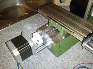
The rear of the Y axis
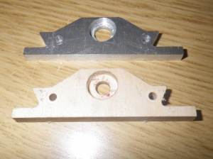
 This was the first piece I did as it was smaller and simpler. It’s milled from 5mm think aluminium and in place of the washer on the standard plastic piece it uses a sealed bearing. The leadscrew diameter is 6mm and the smallest bearing I could find had a 12mm outside diameter and 4mm thickness. Perfect. Following other people’s builds, it’s a standard radial bearing rather than a thrust bearing. For the small load it’s under that should be fine. Note the wooden practice piece; it’s far easier and quicker to check for fit using some easily cut softwood first.
It was the first piece of metal I’d milled and I was running the feed rate a little too high, especially on drilling operations. I managed to break my 1mm mill, but I suppose that’s all part of the learning curve. It was pretty noisy too. I now wear earplugs whilst milling! Fitting this increased my Y axis travel from 48mm to a much improved 68mm! 2cm might not sound like a lot, but it makes all the difference.
One thing I’m not keen on is that the shroud over the Y axis leadscrew no longer fits. This means that all the swarf from milling can stick to the leadscrew and increase wear on the delrin under the table. This will probably lead to increased backlash. I’ve not noticed anyone else with a solution to this – including the professionally converted Usovo machines. Maybe something I’ll just have to live with.
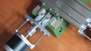
The front of the Y axis
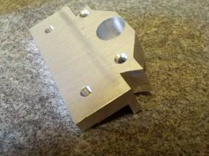
 Now this was a more adventurous piece! It seemed sensible to make a similar piece and let the table slide over the front end stop. However, the difference between this and the rear is that teh stepper motors are mounted to it. Even if I created a piece, the two screws used for the diagonally mounted motor would foul the sliding table. Could I perhaps use a smaller NEMA17-sized motor rather than my NEMA23s? No. This would still cause a problem. Some other conversions (Jarkman’s for instance) mounted the motor square rather than diagonally – here the bottom mounts would be fine but the top two even more of a problem. The I hit on the idea of using just the two lower mounts. Whilst it wasn’t supported evenly it looked no worse than some of the extended ones. I had to give it a try.
 The piece was milled out of a 15mm think chunk of aluminium. I was being a little overcautious with the feedrates and cut depths now and this took ages! I got very bored standing there with a hoover and a vacuum mount is well overdue. The thickness is for two reason. Firstly I had to cut 8mm off the back at the rear because the mill base sticks out a bit further than the table. Secondly, I wanted a firm mount for the motor (now into 7mm of metal). The bearing is set very deep in the piece. This time I used a bearing that is 13mm OD and 5mm thick. This gave a wide enough hole for part of the original handle to sit in. This is the end result.
The mill now has a theoretical Y axis travel of 91mm. The limiting factor is now actually the distance between the spindle and the back of the mill which is 82mm. Whilst you could move the material 92mm, any piece of the work that would be millable at it’s full positive extend would hit the mill before it ran out of travel. All in all, I’m very happy with the result. I’ll attached the CamBam files for these pieces once I work out how to in WordPress. In the meantime contact me if you’d like a copy. Note that the tolerances are very tight. I decided to try giving the mill a bit more support on its travel so the piece may need a little gentle filing before fitting. Also, the pieces have sharp internal corners and the tool radius means that a little filing will be needed here too.


Very nice conversion to extend the table travel. How do you find the rigidity of the motor mount ? I’d certainly be interested in a copy of the CamBam files. Thanks
The rigidity is fine. To be honest it worked out better than I’d expected. The CamBam files should be available at https://docs.google.com/folder/d/0B4auczqs5G64aVkzTEpScXNXMzg/edit
Thanks. One thought on the leadscrews – by making a right hand delrin nut, standard 6mm threaded bar could be used for longer lead screws. I had been intending to do this until I saw your neat idea. But the right hand thread conversion might be useful when the delrin nuts need replacing as standard 6mm tap is much cheaper than the left hand ones.
One other thought – the table could be moved forward to make the last bit of extra Y travel usable – not sure if this is worth the effort though
I did try getting a spare X-axis leadscrew (right hand thread and longer) from Proxxon but got nowhere. I’m not sure where else to get accurate 1mm pitch acme threaded leadscrew from. Removing the stops on the table travel would be necessary anyway, so there didn’t seem any point in replacing the leadscrew at the moment. If it wears out though I’d definitely consider it.
Moving the table wouldn’t make any difference. The limit is between the spindle and the very solid vertical support for it. Moving the table forward would have made the front bracket simpler to mill though.
I’m attempting to create one like this for my father. I’ll report later this month with progress.
If you have any problems then let me know. I’d recommend making one out of wood first to check for fit. You can up the feedrate considerably and have a test one made in no time. Far quicker and easier to spot a mistake that way.
Hi,
Very nice modification !
I plan to do the same on my MF70. Is it possible to have step files ?
Thanks
Hi again,
What stepper motor do you use?
Do you know their holding and detent torque ?
Thanks
Good job.
I wonder though if I’d be possible to extend the travel lenght MUCH more (to around 30-35cm on X and Y axis, Z axis doesn’t really matter) by replacing the “Threaded rod” (I think that’s its name in English) with a longer one as well as doing the conversion you proposed.
I though about doing this on the “KT150”, but I don’t really know if that would work (since I also have to somewhat fix the driller to the “KT150” table). I read about doing a complete DIY unit from scratch, though that’s a bit out of my area of expertise (and equipment needed).
I know this may seem a bit overkill for DIY but while 70-100mm axis travel length may be enough for small electronics projects, they may not be enough for bigger ones (power electronics, to say one).
Thanks for your article about this very nice modification. I am just finishing my wooden practice piece and it seems to be running fine. What mill did you use ? I am using a 3mm head mill but I want to be sure before going for the metal version.
I think I also used a 3mm end mill but maybe it was 2mm. Don’t forget to reduce your speed and depth of cut for metal. Let me know how it turns out.
Today I could finally see the table slide over the brand new aluminium extensions.
First of all, I believe that Proxxon has changed the machine design. The CamBam files locate the bearings 5mm above the screw holes but in my machine I have only 4mm. That made me do al the milling work a second time.
Secondly, the precision of my aluminium workpieces was not tremendous. It took a lot of manual fine tuning to get the things fit. I believe that vibrations or bending of the end mills caused these problems.
But anyway, thanks again !
I’m glad you got it working. I had to do a bit of filing too. It’s a large chunk of metal for such a small mill and I’m still no expert at milling.
I find it’s always worth doing a quick check using scrap MDF (at a higher feed rate if you want) before committing to cutting metal. It let’s you check the fit for any mistakes.
Hi. I’m beginner with cnc and trying to use your cambam files. Rear insert was easy. But how do I cut front using your cambam files? Cut from one side (Y axis front plate – rear inset.cb) but what about cutting the other side? Missing cambam file or should “Y axis rear plate v2.cb” be modified to match what’s needed?
Thanks for you comments. I’m sorry – there was a file missing.You need to cut out the piece using “Y axis front plate.cb” (now added) and then turn it over and mill the rear insets using “Y axis front plate – rear inset.cb”
Please double-check the toolpath these generate as I was still tinkering with my mill at the time and very much an amateur. The mill was also set to only run at a maximum of 100mm/min at the time so I would have got away with any erroneous rapids. I now happily use 800mm/min for rapids and could probably go faster if there was a need to.
I suggest that if you’re making one that you first cut one from a soft wood to check for fit etc. before committing to metal.
Thanks. Now I have front Y axis plate replaced 🙂 (minor adjustments were needed like lowering bearing and motor mounts down 1mm; was mentioned in comments earlier)
800mm/min for aluminium on MF70? I’ve tried doing 250mm/min, 2mm depth with 3mm cutter and ended up with broken cutter in middle of first cut. 500mm/min, 5mm depth, 3mm cutter was fine for MDF.
If you can share more hints on working with MF70 then it would be great.
ps. now how to figure out how to protect lead screew
No – 800 for rapid movements when not cutting! I tend to cut about 200 for soft materials like wood or acrylic and only 50 or 100 for metal. I would rather be slow than break bits.
My only tips are to start slowly and have your finger on the emergency stop if you’re not 100% sure. You can always use the feed rate override if it looks too slow. Also, end mills aren’t the best for drilling.
I still haven’t protected my leadscrew and it seems OK if I vacuum up the swarf as I cut. If you find a good solution then please share.
Hello
I just visited your blog and read your transformation of the MF70. I have one that I converted to CNC 2 years ago. I could really use same extra Y length and I have looked at several solutions. You’re the most similar to what I would like to do. Can you post same pictures of the rear plate assembly?
Can you share the files in DXF format?
Thanks, Vasco Reis
P.S. Nice picture of Lisbon 😉
Hello
I managed to build the first extension plate. So I have 65mm of Y :-). I have done it in black POM (Delrin) its working fine and it looks good . Its easier to cut and I believe doses the same job.
Regards, VCR
I’m glad it worked. I agree Delrin is probably a good choice.
The front plate gives you a bit more but you are still limited by the distance from the spindle to the column, so maybe not as important. It’s also harder to machine.
65mm Is sufficient for the moment. I have the feeling that the ball bearing helps the machine to run smuder. I’m considering rebuilding the other plates to accommodate ball bearings.
Regards VCR
Many thanks for this blog and the associated files, successfully fitted the rear Y plate and it’s all running perfectly (the Y axis wasn’t before, it was noisy, click, click, click all the time). This was my first job in metal on the MF 70 and it helped highlight problems with the way I was doing things. That said the first attempt is the one fitted and working, I’ve got the extra 21mm travel on the Y axis, and no more click, click, click.
I’m that impressed I’m considering doing the other 3 plates so I can fit real bearings rather than the supplied washers.
Again, Many Thanks.
For anyone interested, goopyplastic did a 3D printed conversion that uses bearings on all 3 axis and makes a few other tweaks that improve performance. Ideas could be taken from there, stl’s converted for milling or if you have a 3D printer, the 3D printed parts work great. I have no had any problems with rigidity. I hope it’s okay to post a link, but if you google bubblegum cnc MF70 conversion, you will find it on thingiverse, along with a series of videos on youtube.
http://www.thingiverse.com/thing:33799
No problem posting a link. It’s nice to see other conversions.
I think I prefer milled over 3D printed as it feels more solid. Also you’ve got a mill so you might as well use it! I suppose if you have a 3D printer and haven’t CNC’d your mill yet then it’s an easier solution.
Of all my tools I find I use the 3D printer the least. That’s just personal preference though.
What are the dimensions of these plates? I opened the Y front plate, and for some reason both CamBam and exported DXFs have the size as 1016mm tall!
I haven’t got the dimension on me right now. I’d suggest you probably measure a reference on yours (e.g. spacing between screw holes) and resize it. In fact it might be worth measuring your own properly – I seem to remember someone said that his seemed slightly different to mine.
hello sir. can we extend X-axis also?
Pingback: CNCがやっと完成の域に | 電子工作とマラソンと音楽と
Are the cambam files still available?
I found them. Let me know your email address and I’ll send them to you.
It is good to know that this project is still alive 🙂 My CNC still works and without problems. The option for the PON-C MF70 was a winner.
Regards VCR
I was wondering if you have 3D models of these mods and would you be willing to share them?
Sorry. I can’t find them. It was 9 years ago and I no longer have the MF70.