I’d be happy to share the design files if anyone is interested, but I doubt anyone has exactly the same setup as me. I also altered things as I went, so I don’t have any “final” versions.
Category Archives: MF70
CNC mill alignment camera (version 1.0)
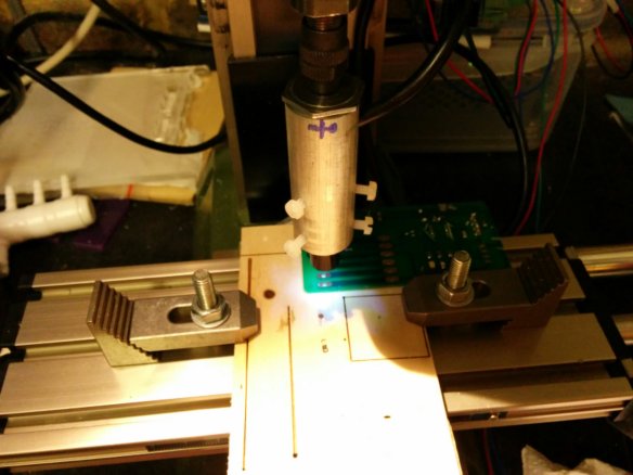
Since switching from milling PCBs to etching them, one of the most awkward steps is getting accurate alignment for drilling and cutting out the boards. Mounting a camera on the spindle isn’t an original idea, but after sporting some tiny endoscope cameras on eBay (10mm dia, 40mm long) I thought I’d give it a go. A good excuse to use the new lathe too.
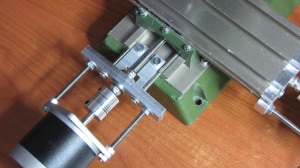
The design is pretty simple. I drilled out some aluminium bar stock to 12mm, with one end slightly narrower and tapped to M12. Then I turned down a M12 bolt to for in the 3mm collet I use with my end mills. A slot at the top is for the USB cable and two sets of three nylon screws allow for accurate alignment.
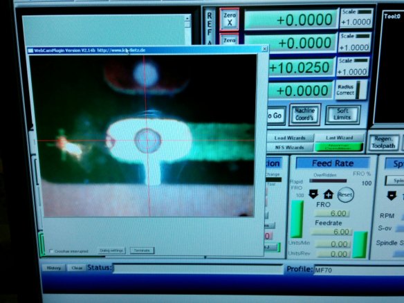
As you can see, a Mach3 video plug in makes it very easy to set the origin on a PCB or other work. Unfortunately it’s a bit long so there’s only just enough room to use with flat stock. I considered mounting it to the side of the spindle (with a known offset) but that didn’t seem right. A more compact version 2.0 is already planned using just the guts of the camera.
Custom Fisher Price records
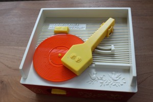 I decided to turn my recent interest in CNC milling into something useful. I was discussing with a colleague at work the old Fisher Price toy record player that everyone seemed to have as a kid. It dawned on me that it might be possible to reverse engineer the records and CNC mill or 3D print a new record.
There was an interesting competition on Instructables with a really nice 3D printer as a prize, so I got to creating a CNC milled version and documenting it there. Rather than repeating myself, I’ll just point you there – http://www.instructables.com/id/Custom-records-for-a-70s-toy-record-player/
Whilst I didn’t quite manage to win the star prize, I did win a really nice home 3D printer – the UP.
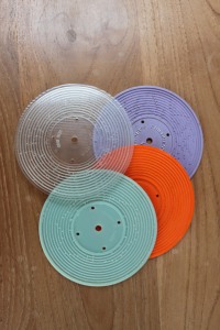 Inspired by the win, I then adapted many project to 3D print the records instead. This is also documented on Instructables – http://www.instructables.com/id/3D-printing-records-for-a-Fisher-Price-toy-record-/
I just missed out on winning a laser cutter with that one, despite getting over 37,000 views. Nevermind. I ended up buying one anyway.
Extending the MF70’s Y axis
The MF70 is a great machine and ideal for a beginner conversion. However, I soon found one limitation – the Y axis is limited to a tiny 48mm. I kind of assumed that the 70 in the name of the mill (and also the separate KT70 compound table) meant 70mm, but it seems not.
A few people have com across this and developed their own solution – notably Retromaster and preconverted machines from Usovo. Whilst these look good and inspired me, one thing I didn’t like is the way the endstop and stepper motor seemed to hang even further off the machine than with a “normal” conversion. They also require a longer leadscrew. I’ve had a lot of trouble finding a suitable leadscrew replacement that isn’t really expensive. I even tried getting a replacement Y-axis leadscrew from Proxxon; it’s longer and also a right handed thread.I had an idea for a solution that I thought was a little simpler. Rather than moving the end stops further out, I’d reduce their size so that the table could slide over them. They’d still be used for fixing the end of the leadscrew but no longer stop its travel. Nobody else seems to have done this but as the leadscrew is attached only in the centre of the table it shouldn’t be a problem. Other conversions had proven that stability of the table wouldn’t be affected. It seems I’d fallen into the “trap” that most people do… the first things I mill seem to be parts for my mill! Never mind.
The rear of the Y axis
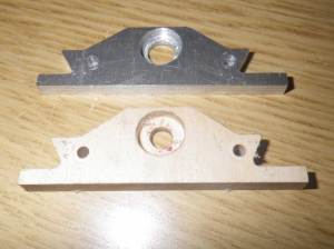 This was the first piece I did as it was smaller and simpler. It’s milled from 5mm think aluminium and in place of the washer on the standard plastic piece it uses a sealed bearing. The leadscrew diameter is 6mm and the smallest bearing I could find had a 12mm outside diameter and 4mm thickness. Perfect. Following other people’s builds, it’s a standard radial bearing rather than a thrust bearing. For the small load it’s under that should be fine. Note the wooden practice piece; it’s far easier and quicker to check for fit using some easily cut softwood first.
It was the first piece of metal I’d milled and I was running the feed rate a little too high, especially on drilling operations. I managed to break my 1mm mill, but I suppose that’s all part of the learning curve. It was pretty noisy too. I now wear earplugs whilst milling! Fitting this increased my Y axis travel from 48mm to a much improved 68mm! 2cm might not sound like a lot, but it makes all the difference.
One thing I’m not keen on is that the shroud over the Y axis leadscrew no longer fits. This means that all the swarf from milling can stick to the leadscrew and increase wear on the delrin under the table. This will probably lead to increased backlash. I’ve not noticed anyone else with a solution to this – including the professionally converted Usovo machines. Maybe something I’ll just have to live with.
The front of the Y axis
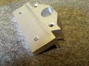 Now this was a more adventurous piece! It seemed sensible to make a similar piece and let the table slide over the front end stop. However, the difference between this and the rear is that teh stepper motors are mounted to it. Even if I created a piece, the two screws used for the diagonally mounted motor would foul the sliding table. Could I perhaps use a smaller NEMA17-sized motor rather than my NEMA23s? No. This would still cause a problem. Some other conversions (Jarkman’s for instance) mounted the motor square rather than diagonally – here the bottom mounts would be fine but the top two even more of a problem. The I hit on the idea of using just the two lower mounts. Whilst it wasn’t supported evenly it looked no worse than some of the extended ones. I had to give it a try.
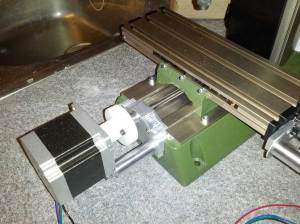 The piece was milled out of a 15mm think chunk of aluminium. I was being a little overcautious with the feedrates and cut depths now and this took ages! I got very bored standing there with a hoover and a vacuum mount is well overdue. The thickness is for two reason. Firstly I had to cut 8mm off the back at the rear because the mill base sticks out a bit further than the table. Secondly, I wanted a firm mount for the motor (now into 7mm of metal). The bearing is set very deep in the piece. This time I used a bearing that is 13mm OD and 5mm thick. This gave a wide enough hole for part of the original handle to sit in. This is the end result.
The mill now has a theoretical Y axis travel of 91mm. The limiting factor is now actually the distance between the spindle and the back of the mill which is 82mm. Whilst you could move the material 92mm, any piece of the work that would be millable at it’s full positive extend would hit the mill before it ran out of travel. All in all, I’m very happy with the result. I’ll attached the CamBam files for these pieces once I work out how to in WordPress. In the meantime contact me if you’d like a copy. Note that the tolerances are very tight. I decided to try giving the mill a bit more support on its travel so the piece may need a little gentle filing before fitting. Also, the pieces have sharp internal corners and the tool radius means that a little filing will be needed here too.
Proxxon MF70 CNC mill conversion
Making my own PCBs
I’d decided that I’d had enough of nasty stripboard creations and would make my own PCBs. Designing and sending off to somewhere like Seeed or BatchPCB seems Ok if you’re based in the US and have a use for 5 or so boards, but most of mine is a one-off and nowhere seems to do a reasonable price if you’re in the UK. That and I’m too impatient to wait 2 weeks for a board. I was looking into laser printer toner transfer and etching but then stumbled across some CNC mill conversions that seems doable and not too expensive. The main one that caught my attention was http://www.jarkman.co.uk/catalog/cnc/mf70.htm but there are plenty more linked from there. He was very helpful and gave me a few pointers.
What I used
The MF70 seems like a great price as a manual mill. I paid about £270 and budgeted about teh same again to convert it to CNC. Ready made CNC systems seems to be thousands.
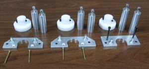 I decided to make things as easy as possible for myself. I bought a nice stepper motor mount kit on eBay from a seller called *mbbilici*. All very nicely made as you can see from the photo. I’d thoroughly recommend this kit for getting started quickly.
I also bought a kit containing 3 stepper motors, a PSU and a TB6560-based stepper motor controller board. Just after I got this I discovered how much hassle some people have had with the TB6560 boards. To be honest mine is working fine but you can read about other people’s troubles here so I can’t really recommend it. I suspect I’ve been lucky. It’s probably best avoided and I intend to replace it when I can.
Well, here’s the finished product. Nothing too different from every else’s conversion, but it’s exactly what I was after! It still needs a bit of tidying – neater wiring, limit switches, etc. I’m sure I’ll be tweaking and adding to it for a while to come. 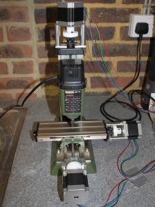
The “standard” way to control CNC stuff is using Mach3 software running on a PC and communicating with the stepper driver over a parallel port. My brother had a suitable PC lying around, so I decided the quick and easy approach would be best. It really does feel like a solution out of the 90s though – especially when you see the nasty UI for Mach3! It reminds me of the old Visual Basic days when everyone had red and green buttons. Truly horrible. But it works well for now.
On the design side I can thoroughly recommend CamBam. Very easy to get started with and very professional. Nothing like Mach3.
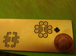 Well, it may not have been the most adventurous of conversions, but I was up and running within a week or two and carving random chunks of wood. With a few more peices of software – Cadsoft Eagle for PCB design and PCB-gcode to convert this into instruction for the mill, I was turning out some PCB and surprising myself with the accuracy of this little mill. The photo is of a SOIC breakout board that I made for a friend. I was using a 1mm bit which was far to large for the job, but I was still impressed with my first attempt.
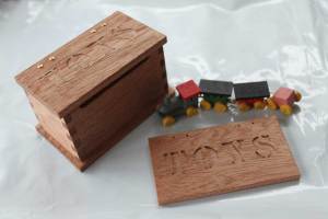 My wife wasn’t too keen on my new hobby, but saw some benefit to it once we’d designed and made a toy box for my 4 year old niece’s dolls’ house.

