
Why Hue?
I’ve been thinking about some how automation for a while but have been wondering how the best way to go about it would be. I was thinking of a mesh network of battery powered switches using Sub-1GHz 6LoWPAN – hence the recent mucking about with Contiki OS. However, I decided to go for a couple of Amazon Echo Dots in a recently Black Friday promo and decided that I should get an off-the-shelf solution working whilst I spend the next couple of years making the “perfect” one.
After a little research I decided on the Philips Hue system. These are Zigbee controlled bulbs that you leave permanently powered. The system isn’t perfect – but better than the others on the shortlist. Z-Wave is proprietary. LightwaveRF leeches power through the bulbs and you can’t tell if the device heard your command or not.
Philips did get some grief for locking out other Zigbee devices but seem to have reversed that. Obviously other devices don’t quite get the love that Philips products do, but they’re OK. On the plus side, Philips have documented a nice API at the hub level that allows you control their bulbs from the outside of the Zigbee network. They are however understandably protective of things on the inside.
On the negative side, Philips do not have a device that can control an arbitrary light. I’ve got a floodlight and some track lighting in the workshop. Can’t do those. My bathroom has about 9 GU10 bulbs in the ceiling – possible but 9 x £25 is an unpleasant £225.
What’s the plan?
My plan is threefold.
- Firstly, I want to take one of the cheaper £15 single colour bulbs apart and see what’s what.
- Secondly, I want to extend the Hue ecosystem but by “gently” hacking it – i.e. buying a Philips Hue product, leaving their hardware and code more or less intact but adding what I want to it.
- Thirdly, I’d like to do some Zigbee work. Maybe make a slightly more feature rich switch that those they supply. Maybe vreate a Zigbee light that Philips are happy to work with
Anyway, I’ll start with the simplest so I have something working and take steps from there.
What’s inside then?
 Before I start, let me say that I was greatly helped by the work of others such as Colin O’Flynn. I’m not the first to tear open a Hue bulb, but it turns out my UK spec bayonet fitting LBW010 is a bit different to those before.
First you have to remove the plastic top. I used a small hacksaw, but it eventually came away in one piece when the glue gave way. I think a little bit of squeezing in the vice might have been all that’s needed. It’s not like I’m going to put it back together anyway so not too important.
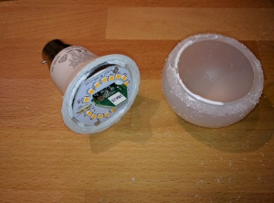 It opens up to reveal the LED board (with metal heatsink) which is attached with a couple of screws and more glue. I tried a heat gun to soften the glue but that didn’t help. In the end just some levering with a small screwdriver did the trick. The LED board separates nicely from the logic board and has a simple 0.1″ pitch SMT header for this. Very useful. Some quick measurements show the LEDs have a voltage of 24.4V and a current of 350mA. I assume there’s a constant current supply on the PCB but I’ve not taken the time to track that down yet.
One thing worth noting on the B22 bulbs is that the two main contacts for mains power are actually solder. Before pulling the PCB out you should melt the solder on these. I didn’t and ripped on of the 15Ω resistors that are used as fuses from the PCB. Easily replaced, but annoying that I was heavy handed with this.
 Other bulb teardowns revealed an Atmel ATMega2564 (AVR microcontroller with Zigbee) and a ST HVLED815PF (LED driver) but my bulb seems to be different. Inside is an Atmel SAM21R21E18A – the same ARM microcontroller with Zigbee as found in the Bridge. I couldn’t find a LED driver IC so this is perhaps constructed using discrete components. I didn’t look very hard though. I will try to get a better photo later.
There are a number of test pads. Careful probing a track tracing shows they are as follows:
TP1 – GND
TP2 – PA30 on the microcontroller. This is SWCLK for debugging
TP3 – PA31. This is SWDIO for debugging
TP4 – Serial TX (more on this below)
TP5 – Serial RX
TP6 – main output to the LED
TP7 – 3.3V. This is the output from the 3.3V regulator and input to the microcontroller. It can be used to power the board but you’re better off using TP25.
TP8 – RESET for the microcontroller
TP11 – GND
TP25 – Power in to the LM2204 VLDO regulator. It takes about 24V when powered from the mains but is happy when powered with 5.1V from USB for hacking about.
What was most interesting initially was the output on TP4. It contains debug messages from the Atmel Zigbee stack and on power up you get something like this. Output is 115200 8N1 and line endings are CR only.
[Log,Info,S_LightConfiguration,Configuration Data OK, crc=0x60083D2F]
[Log,Info,S_DeviceInfo,Default Flux table]
[Log,Info,S_DeviceInfo,ProductId: Philips-LWB010-1-A19DLv3, ModelId: LWB010]
[Log,Info,S_DeviceInfo,ZLLDeviceId: 256(DimmableLight), PwmChnl: 1]
[Log,Info,ConfLightLamp,devsig=0x10010318]
[Log,Info,S_DeviceInfo,Booting into normal mode...]
[Log,Info,S_DeviceInfo,DeviceId: ConfLight]
[Log,Info,N_Security,LIB4.6.135]
[Log,Info,N_Security,KeyBitMask,0x0012]
[Log,Info,AL_OTAUpgrade,containerVersion=0x01000B00]
[Log,Info,ConfLightLamp,errs=0,lastErr=RST@0]
[Log,Info,ConfLightLamp,Platform 0.85.0: r19111, BC_V3.3.0_2.4_M: r19111]
[Log,Info,ConfLightLamp,Product version ConfLight fw_ver: 1.15.0_r18729,built by LouvreZLL]
[Log,Info,A_Commissioning,NwkAddr: 0x32BE, Ch: 20, Pan: 0x5DE4, NwkUpdId: 0, ExtPanID: 8D80F343023D3B9E]
[SYS,Info,Transmit buffer full]
[TH,Ready,0]
[Log,Info,N_Connection,Starting discovery for updated networks]
[Log,Info,N_Connection,Discovery for updated networks completed]
This is interesting and my initial thoughts were that I could capture any output when light levels are set and make use of these. Unfortunately, there’s nothing interesting once the bulb is connected and running.
 I decided that there must be some more useful output from the microcontroller going to the LED drive circuitry so decided to probe the pins whilst changing output. Bingo! It seems that we have a nice PWM output on PA17 with the duty cycle representing the brightness.You need to move a large electrolytic capacitor out of the way to get to the IC and it’s pin 18 (the second one up from the bottom on the RHS). I haven’t traced it to a test point or other more accessible location yet, but I will.

Pingback: Philips Hue – simple relay hack | 0xFRED
Pingback: Philips LED A19 Lamp Deep Dive Teardown | Since 1989